In this part I will describe the hardware side of the Punch Acceleration Sensor and the next part will be about the software.
You can download Eagle schematics and printouts here
Here’s the basic hardware schematic (click for pdf version):
These schematics use SparkFun Eagle Library for the Arduino board so the pins shown are for the Arduino board and not ATmega328. You can see how those pins correspond to ATmega328 pins by downloading schematics from Arduino Duemilanove specs page.
ADXL193 sensor comes only in a surface mounted package but fortunately SparkFun sells it already soldered on a breakout board with decoupling capacitor. The sensor has 4 pins: Gnd, Vcc, Vout and ST. The ST signal is the self-test feature and when set to logic HIGH will apply electrostatic field on the movable frame within the chip and causes Vout to change to indicate acceleration.
The ADXL193 is connected to the main unit using pair of 4 pin right angle connectors (Tyco Electronics 640457-4), connector receptacle housing (Tyco Electronics 1375820-4), connector contacts (Tyco Electronics 1375819-1), and a flat under-carpet phone cable (don’t have the model number, bought at Home Depot)
AD7680 16 bit A/D Converter also comes only in SMD package, so i had to purchase a breakout board and solder it myself (Capital Advanced Technologies 33108). The AD7680 has standard Vdd, Gnd pins, Vin for input voltage and following SPI interface pins: CS(neg), SDATA, SCLK. ATmega328 supports SPI interface on SCK (PB5), MISO (PB4), MOSI (PB3), SS (PB2) pins, which correspond to 13,12,11, and 10 pins of the Arduino board. Therefore, CS of AD7680 is connected to pin 10 of Arduino board, SDATA to 12, and CS to 10.
SN74HC594 8 bit Shift Register. As I mentioned in the first part of this post, ATMega328P did not have enough digital pins to drive all of the 7 segment LED and even through i could probably use some of the analog pins i wanted to experiment with shift register so i went that route. The reason shift register help save up pins is that it only needs 2 pins to program it and it outputs 8 lines of data. You can stack them in series and output as many lines as you would like. There are also input versions of this chip, so you can use it to read multiple lines of data as well. Now it takes 2 pin for the most simplistic design (which i took): one pin for clock and another for data. The disadvantage of this method is that while you are shifting data out the output values of the register are unstable – 1st bit of data travels through all 8 outputs until it arrives at it’s place. SN74HC594 has a solution to that in the way of storage registers and RCLK pin. The way it works is that SN74HC594 actually has 16 1bit registers: 8 data and 8 storage. When you shift data out it is stored in data registers while output is read from storage registers. So if you keep RCLK pin unchanged when you are shifting out the data and when it’s all done toggle RCLK from low to high SN74HC594 will output old data until that upward edge and at that point move data from data to storage registers and start outputting new data. There are even more advanced types of these chips called I/O Expanders (example Microchip MCP23018-E/SP). In these chips, each pin can be independently configured as either input or output and you can set triggers to be fired when input data changes. For the purpose of this project a simple register with SCLK and RCLK tied together was sufficient.
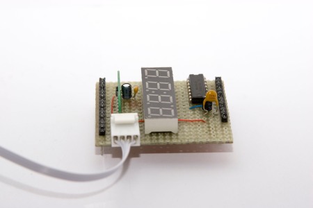
7 segment 4 digit LEDis a generic 7 segment led from SparkFun. In order to control the LED you set one of the digit selection pins to HIGH and pins corresponding to the segments of that digit that you want to be turned on to LOW. This coding scheme allows only one digit to be “on” at the time so micro-controller has to rapidly switch between digits to maintain illusion that all of them are lit. As with all LEDs controlling current is important as too little current will make it too dim and too much (more than 20mA) will burn it out. The recommended practice is to put 330 Om resistor in series with LED, however an alternative solution is to limit amount of time LED current is on. This project implements the latter solution, so no resistors are necessary.
Miscellaneous Components. A 250 mA thermistor (Tyco Electronics RXEF025) is placed in series with power supply for circuit protection. A 100 uF (micro farad) capacitor is placed in supply/ground rails, 10 uF and 0.1 uF capacitors are placed in parallel on the Vdd and Gnd of AD7680 A/D converter as recommended by AD7680 spec sheet.
Putting it all together
Putting initial circuit prototype was very easy and fast thanks to the solder-less breadboard and jumper wires:
I actually built a solderless prototyping shield for Arduino out of Freeduino Protoshield KIT for Arduino and a medium breadboard.
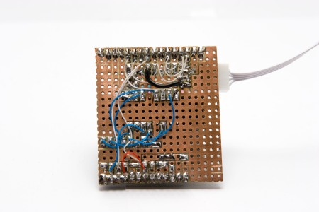
The problem with prototype was that the jumper wires didn’t hold all that great and were constantly flying out of the board. So the next step was to build something soldered down. I have considered available solutions and there was much to choose from: single or dual copper clad, not copper clad, pre-drilled, pre-etched, high quality from pcb house, etc… I thought I would try my luck with single side pre-drilled but not etched board i found on DigiKey. The idea is to lay out components in the most compact way and cut groves between the pads on the copper side. I have also attempted to use the existing copper for some of the connections as well:
the rest of the connections were made using 30 AWG wires. I have attempted to run those wires through the top of the board at first but found it too time consuming. In retrospect a faster way would be to just make sure every pin of a iC component has a connected empty pad next to it and wire everything with bottom side wires and not to worry about making connections using copper – it took to much time to lay those paths out and in the end i could not route that many of them anyway – soldering wire is faster. The groves between the pads were cut using Dremel and an engraving attachment.
More pictures:
I hope you have found this useful. If you have any questions please feel free to comment or shoot me an email.
Update – Errata:
Thank you Mark Z. for finding these:
- Schematic diagram has incorrect labels on AD7680. It should be as follows: 5 – CLK, 7 – DATA, 8 – CS. Pin 6 should be pin 7. Wiring diagram and code are correct.
- Schematic diagram is missing power and ground connections to shift register: GND pin 8 and VCC to pin 16. Wiring diagram is correct
Next: Part 3 – Software
Previous: Part 1 – Overview
Aleksey
Tags: Accelerometer, AD7680, ADXL193, arduino, ATMega, diy, electronics, Shift Register


April 15, 2010 at 10:22 am |
[…] after finishing his Makiwara punching bag, [Abieneman] wired and programmed an Arduino to an accelerometer to find out just how much acceleration (and with some […]
April 15, 2010 at 11:00 am |
[…] after finishing his Makiwara punching bag, [Abieneman] wired and programmed an Arduino to an accelerometer to find out just how much acceleration (and with some […]
September 4, 2011 at 10:17 am |
I’m an electronics newbie so please forgive my ignorance. Is the output from the A/D converter PWM? Want to connect to a Basic Stamp 2. Thanks.
September 4, 2011 at 11:48 am |
No, the AD7680 A/D converter outputs data in serial format – see https://abieneman.files.wordpress.com/2010/04/ad7680-timing-diagram.gif
However, if i read documentation correctly, Stamp 2 should be able to handle it with the SHIFTIN command with MSBPOST mode.
October 12, 2011 at 9:08 pm |
Aleksey,
I made an error. I purchased the 6 pin version of the ADC7680. I noticed from your pics that you have the 8 pin version and breakout. Will this be an issue? Why did you choose the 8 pin? Also, the schematic doesn’t show a VDD or a VSS connection to the ADC. Is this an assumed connection? I’ve got it all hooked up to my BS2 and have the ADC hooked up to VDD and VSS. PIN 4 from the accelerometer goes to the input of the ADC right? Sorry for all of the questions. My debug terminal is currently returning the value of 8191. Contacting forum at Parallax to get some help with how to write your code equation in PBASIC. Thanks.
October 13, 2011 at 11:02 am |
6 pin version is fine – it is the same part but in a different package. Just make sure you connect to right pins as they are different on 6 pin and 8 pin versions.
The power and ground to AD7680 are shown on the middle bottom of the schematic separately from main part.
You are correct about pin 4 from SparkFun breakout board going to input pin of AD7680 (pin 3 of 6 pin package and pin 4 of 8 pin package).
If the output 8191 is in hex then it’s correct indicating no acceleration. If it’s decimal then it’s too low. Email me entire output and i can tell more.
I’ve also added other corrections to the schematic at the end of main post.
January 15, 2016 at 8:33 pm |
Your schematic shows two 100uf capacitors, while your text says: “A 100 uF (micro farad) capacitor is placed in supply/ground rails, 10 uF and 0.1 uF capacitors are placed in parallel on the Vdd and Gnd of AD7680 A/D converter as recommended by AD7680 spec sheet.”
Which is correct?
Thanks,
January 18, 2016 at 5:25 pm |
The 10 and 0.1 uF are what spec sheet says. I don’t recall why I used 100 and 0.1 instead but most likely because I didn’t have 10 uF one or wanted to keep parts list short. Just a reminder that spec sheet recommends low ESR capacitors.
September 4, 2018 at 10:11 am |
Hi! I really find your project very interesting. I do have some questions.
1. Would it be possible to measure the acceleration on X and Z axis (like left and right and forward backward) since I might try to use it for other things like a kick and etc. Maybe use a different accelerometer?
2. Would it also be possible to automatically add up data for a set amount of time? like add all the data it accumulates for 60 secs then it stops recording. Would you need to do something about the Arduino programmin instead?
Hoping to hear from you! thanks!
October 1, 2018 at 11:03 am |
To capture acceleration on other axes you’d need a 2 or 3 axis accelerometer chip (or couple of single axis accelerometers, however that would probably be more expensive and complex).
Yes, you can change how data is collected through Arduino code, there’s a limit on how much you can accumulate due to limited arduino memory though but often times you’ll be fine (for example to calculate an average you don’t need to keep all samples but just a sum of values and number of sample)
August 31, 2020 at 11:11 pm |
Hello sir, i want ask. What unit is the punch power displayed? Newton maybe?
September 5, 2020 at 1:50 pm |
It is in “g” acceleration units.